A gamma radiography crew does far more than place a source beside a weld and expose film. The job involves technique planning, controlled-area management, image-quality checks and qualified interpretation, so you can judge whether the examination will produce usable evidence rather than an unexplained “tested” result.
Key takeaways
- Confirm the weld map, code, thickness and exposure plan before work starts.
- Check source controls, exclusion zones and radiation-safety arrangements at the site.
- Match each radiograph to the weld number, location and exposure record.
- Ask how defects, repeat exposures and acceptance decisions appear in the final report.
How the job is planned before the source arrives
Before the source arrives, the gamma radiography testing process is fixed from the drawing and weld map, not improvised at the worksite. The plan records the material, thickness, weld geometry, construction code, required coverage, access and number of exposures.
1. Confirm access to both sides of the weld, source-to-object distance, beam angle, detector position, required sensitivity and exposure count. A pipe circumference may need several shots rather than one incomplete image.
2. Select the source for thickness, access and image quality. Iridium-192 suits many fabrication and weld thicknesses; cobalt-60 suits substantially thicker sections; selenium-75 helps where lower photon energy and a smaller radiation exclusion zone are advantageous.
3. Choose film, computed radiography or direct digital radiography, then name the governing documents: ISO 17636-1 for film, ISO 17636-2 for digital radiography, ISO 10675, ASME Section V or the project specification. A quotation saying only “gamma ray weld inspection” leaves coverage and acceptance requirements unclear.
4. Clean the weld before mobilization. Remove scale, spatter, grease, loose paint and coatings that could hide or imitate indications.
5. Provide current drawings, weld numbers, material and thickness records, the weld map and safe access. Gamma radiography is a poor choice with one-sided access, very thin sections, no tolerance for an exclusion zone, or planar flaws better examined by ultrasonic or magnetic-particle testing.
This preparation prevents a source, detector and crew from arriving at a weld that cannot produce an interpretable, traceable image.
What happens when the weld is set up and exposed
1. For a pipe, pressure vessel, tank or structural weld, the crew positions the sealed source inside its shielded exposure device and runs a guide tube toward the source side of the weld. A film cassette or digital detector sits on the opposite, radiation-sensitive side.
Tight geometry can require several shots around a circumference; a panoramic exposure works when the source and detector arrangement permits it.
2. The crew places image-quality indicators, weld markers and location markers beside the weld, checks the collimator and confirms source-to-object distance, detector position and beam angle. These controls determine whether gamma ray weld inspection produces an interpretable image rather than geometric blur or incomplete coverage.
3. In gamma ray radiography testing in Nagpur, the Radiation Protection Officer and authorised radiography personnel establish a controlled area from calculated dose rates based on isotope, activity, collimation, shielding, exposure time and occupancy.
They account for roads, occupied buildings, night work, shutdowns and public access, then post warning signs, barricade the area, control entry, check personal dosimeters and sweep the work zone.
4. A calibrated survey meter confirms conditions before the source is driven remotely into position. After exposure, the source is retracted and locked in its shielded position, followed by another survey-meter check confirming safe dose rates.
If retraction fails, do not approach the device or guide tube; follow the approved emergency source-retrieval procedure with competent radiation-safety personnel.
How the image reveals a defect and proves weld identity
A usable radiograph proves two things separately: which weld it shows and whether the image can support interpretation. During gamma ray weld inspection, the reviewer checks:
- Weld number, location markers, film-side or source-side markers, exposure identifier and coverage against the weld map.
- Film density and contrast, or detector response; IQI (penetrameter) visibility; scatter; backscatter; artefacts; and relevant indications.
- An IQI demonstrates achieved radiographic sensitivity. It does not define the permitted defect size; acceptance comes from the specified fabrication code.
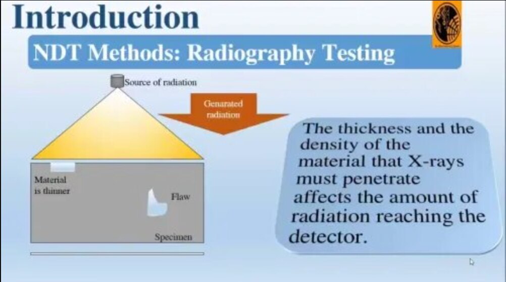
- Porosity, slag inclusion and lack of penetration show most clearly when their geometry creates a measurable thickness change along the beam.
- Tight cracks and lack of fusion can look weak or disappear when they run nearly parallel to the beam. Use ultrasonic testing when planar-flaw detection is critical.
- Undercut appears when its depth and orientation create enough contrast, so a small or poorly oriented indication can be difficult to size.
Film processing is part of the evidence, not clerical work. Control developer activity, processing temperature, fixing, washing, drying and storage; poor control can change density and contrast.
Computed radiography scans an imaging plate, while direct digital radiography sends the image to an electronic detector. Both avoid wet chemistry but still require a qualified technique, image-quality evidence, secure storage and controls against manipulation or accidental overwriting. That discipline makes industrial gamma ray testing traceable rather than merely “tested.”
What the report says about acceptance, repeats and records
A qualified interpreter compares every indication with the acceptance standard named in the purchase order or inspection plan. ISO 17636-1 and ISO 17636-2 govern radiographic technique requirements; they do not decide whether a weld is acceptable.
ISO 10675, ASME Section V and the project specification serve different purposes, while the applicable product or fabrication rule determines acceptance.
| Standard | Primary purpose |
|---|---|
| ISO 17636-1 | Film radiography technique requirements |
| ISO 17636-2 | Digital radiography technique requirements |
| ISO 10675 | Weld imperfection acceptance levels |
| ASME Section V | Nondestructive examination method requirements |
| Project or fabrication specification | Contract-specific acceptance criteria |
The report package should identify the component, weld number, material, thickness, isotope, activity or exposure details, source-to-object distance, film or detector type, technique, IQI result, image or digital file, technician, reviewer and acceptance standard.
It must record each indication, the disposition of every weld, and which welds were rejected, repeated or left non-evaluable. Repeat exposures follow motion, poor density, inadequate IQI visibility, incomplete coverage, damaged film, detector artefacts or an unfavourable beam angle.
Film, computed radiography and direct digital radiography differ in storage, retrieval and review workflow. Ask for the traceable images and report cross-reference; “tested” or a percentage-coverage statement cannot prove what was inspected.
How to choose a suitable Nagpur radiography service
Choose a radiographic testing service in Nagpur by checking its controls, not just its quoted price. Gamma ray radiography testing in Nagpur requires current Atomic Energy Regulatory Board authorization, a named Radiation Protection Officer and documented arrangements for source use, transport, storage and emergencies.
Ask for:
- Authorised personnel details; source and exposure-device records; guide-tube and locking-mechanism checks; survey-meter calibration; equipment maintenance; insurance and safety documentation.
- The emergency source-retrieval arrangement, including competent contacts and the procedure followed if the source fails to retract.
- A quotation naming the acceptance code, technique standard, weld coverage, imaging system, expected records, and responsibility for barricading and access control.
Compare the methods against the actual flaw and site constraint:
| Option | Strength | Constraint |
|---|---|---|
| Gamma radiography | Portable for tanks, pipelines and large structures | Creates an exclusion zone and cannot be switched off like an X-ray tube |
| X-ray radiography | Avoids radioactive-source transport | Needs electrical power |
| Conventional ultrasonic testing | Strong for many planar flaws | Needs probe access and coupling |
| Phased-array ultrasonic testing | Electronic beam steering and imaging | Needs suitable access, coupling and qualified interpretation |
| Magnetic-particle testing | Finds surface and near-surface flaws in ferromagnetic materials | Does not suit non-ferromagnetic materials or deep internal flaws |
Ask who coordinates site security, public-road controls, lifting, power, shutdowns, transport and emergency contacts. Becquerel Industries Pvt Ltd can be considered when one provider must connect the technique plan, site controls, image review and traceable report; verify every record before awarding the work.
Related product
 | Radiography Testing( Gama Ray & X-ray) It is a method of inspecting materials for hidden flaws by using the ability of short X-rays and gamma rays to penetrate various materials. View product → |
Frequently asked questions
How is gamma radiography testing planned before the source arrives?
The plan uses the drawing and weld map to record material, thickness, weld geometry, construction code, required coverage, access and exposure count.
What happens when the weld is set up and exposed?
Technicians position the film or detector and gamma source, establish the exposure geometry, secure the controlled area and expose the weld under the approved procedure.
How does a radiograph reveal a defect and prove weld identity?
Changes in image density show internal features such as porosity, slag inclusion or lack of fusion, while identification markers link the image to a specific weld.
What does the radiography report say about acceptance, repeats and records?
The report identifies the weld, records exposure details and states whether indications meet the specified acceptance criteria, require a repeat or need repair and reinspection.
How do you choose a suitable radiography service in Nagpur?
Compare the provider’s experience with your material and code, source-control and safety arrangements, identification system, reporting detail and ability to work within site access limits.
Keywords