TOFD can reveal and size important planar weld discontinuities, but a signal is not automatically a code-defined critical flaw. You will be able to judge which problems the method detects, where its blind zones and access limits apply, and what evidence to demand before accepting a weld inspection.
Key takeaways
- Use TOFD for planar defects such as cracks, lack of fusion and incomplete penetration.
- Confirm probe access, weld thickness and geometry before selecting TOFD.
- Combine TOFD with pulse-echo UT, radiography or visual examination when coverage is incomplete.
- Ask for scan plans, calibration records, defect sizing data and an inspection report.
Which weld problems can TOFD detect reliably?
TOFD is strongest at finding planar discontinuities: lack of fusion, incomplete penetration and cracks. A transmitting and receiving probe detects diffracted signals from the upper and lower tips of a discontinuity, rather than depending only on echo amplitude.
The time difference between those signals, combined with measured ultrasonic velocity, gives flaw height; encoder data establishes length and position.
| Discontinuity type | TOFD response | More informative companion |
|---|---|---|
| Planar flaws: cracks, lack of fusion, incomplete penetration | Usually strong tip diffraction and useful through-wall sizing | PAUT or angle-beam UT for orientation and surface zones |
| Slag inclusions | Indications are possible, but shape and orientation affect clarity | Radiography or pulse-echo UT |
| Porosity and rounded inclusions | Diffraction can be weak or ambiguous because there are no sharp crack-like tips | Radiography, especially for gas-filled or dispersed pores |
TOFD detects and sizes an indication; it does not decide whether the flaw is critical. That decision requires the construction code, weld category, material, thickness, location and acceptance criteria. Radiography can describe volumetric content better, while TOFD often measures planar flaw height more directly.
A strong-looking B-scan still needs competent interpretation. Lateral-wave, back-wall and tip-diffracted signals can overlap, creating a convincing indication or hiding a shallow one near the cap or root. Poor tracking, incomplete encoder coverage or an incorrect velocity setting can also produce inaccurate dimensions.
For a TOFD weld inspection, review the encoded raw data and the qualified interpretation—not just an accept/reject statement. Anyone researching time of flight diffraction weld problems in Nagpur should treat TOFD as part of a method-based examination plan, not as a universal replacement for radiography or pulse-echo testing.
What happens during a TOFD weld inspection?
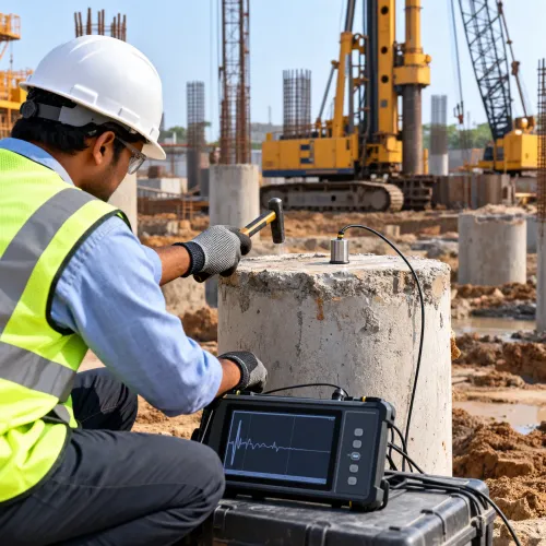
Preparation determines whether TOFD weld inspection measures the weld or the inspection setup. Clean and profile the scanning surface, removing spatter, loose coating and corrosion so both wedges maintain continuous coupling throughout the scan.
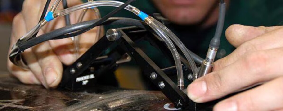
The transmitting and receiving probes sit on opposite sides of the weld. Set their centre separation and index points for the actual material thickness, weld profile and access geometry, then calibrate ultrasonic velocity, time base, gain and sensitivity on a suitable reference block.
- Encode probe movement so every captured A-scan has a known scan position.
- Record the examination as a B-scan or position-versus-time image.
- Verify that the planned scan paths cover the weld, heat-affected areas and required examination volume.
- Review the complete raw or reconstructable data, not an isolated screenshot or an accept/reject statement.
| Check | Record or verify | What failure can affect |
|---|---|---|
| System | Verification before and after scanning | Unnoticed drift or acquisition error |
| Probes and wedges | Probe condition, wedge condition and index points | Incorrect beam placement or coupling loss |
| Scanning | Speed, encoder response and scan paths | Wrong flaw length or position |
For TOFD testing in Nagpur, require the measured sound velocity, calibration records and scan-speed checks with the report. Poor probe tracking, encoder errors, missing paths or an incorrect velocity setting can undermine flaw length, position and height measurements even when the signals look clean.
The reviewer must also assess overlapping lateral-wave, back-wall and tip-diffracted signals before reporting a result.
When do thickness, geometry and access make TOFD unsuitable?
TOFD becomes unsuitable when access, geometry or material conditions prevent both probes from following the planned path. The method needs stable, continuous coupling and enough room on both sides of the weld for the specified probe separation.
- Insulation, supports, coatings, heavy spatter, corrosion, an irregular cap and nearby attachments can block a probe or leave an uninspected strip.
- Restricted pipe layouts can prevent scanning from the opposite side.
- Complex caps, roots and changing thicknesses can distort beam paths and complicate sizing.
- Coarse-grained or anisotropic materials, high attenuation and structural noise can weaken or scatter tip signals.
Near-surface dead zones affect both the scanning surface and the opposite surface. A lateral wave or back-wall response can mask a shallow cap- or root-side flaw, so pulse-echo UT or PAUT is needed for complementary coverage.
Small, tightly closed cracks and unfavourably oriented discontinuities may not produce usable diffraction. A clean-looking scan does not remove that limitation.
Qualify the setup on the actual weld, not a similar job. Confirm the probe angle, frequency, centre separation, gain, sound velocity, index points and scan positions for the weld thickness and configuration. Copying settings can shift the beam away from the flaw or produce a false sense of coverage.
For advanced weld testing in Nagpur, use pulse-echo UT or PAUT to investigate dead zones, roots, caps and unclear indications, especially where access or material structure limits TOFD weld inspection.
How should TOFD be combined with other weld examination methods?
TOFD should sit within a weld examination plan, not replace every method. It sizes planar flaws through the wall and preserves encoded coverage, but it needs access on both sides and gives weaker evidence for some pores and rounded inclusions.
| Option | Strength | Limitation |
|---|---|---|
| TOFD | Direct through-wall sizing, encoded coverage and strong records | Surface dead zones, two-sided access and weak response from some volumetric flaws |
| Radiography | Shows gas pores and rounded inclusions clearly | Radiation exclusion zones, exposure controls and image-quality review |
| Manual UT | Flexible for local investigation | Results depend on operator scanning and are less reproducible |
| PAUT | Steerable beams, weld mapping and near-surface or orientation information | Requires procedure qualification and careful interpretation |
| AUT | Repeatable, high-volume encoded inspection | Less flexible mobilisation and setup |
Use this decision sequence:
1. Combine TOFD with PAUT or conventional angle-beam UT when the weld has cap or root dead zones, complex geometry, uncertain flaw orientation, or mixed planar and volumetric risks. The complementary method investigates areas where lateral-wave or back-wall signals mask shallow flaws.
2. Add radiography when porosity, gas pockets or rounded slag inclusions are a significant risk. Use radiation exclusion zones, exposure controls and image-quality review; do not treat a clean TOFD record as proof that volumetric content is absent.
3. Select AUT for suitable production setups requiring repeatable, high-volume encoded scanning. For TOFD testing in Nagpur or advanced weld testing in Nagpur, tie every method, procedure and acceptance decision to the governing code and stated acceptance criteria.
What should you ask for when buying a TOFD service in Nagpur?
Buy the deliverables, not a certificate. For time of flight diffraction weld problems in Nagpur, ask the provider to put the examination limits and audit trail in writing before mobilisation.
- Request a scan plan stating weld thickness, material, joint geometry, probe frequency and angle, centre separation, index points, scan positions, scan speed and a coverage drawing.
- Ask for the governing acceptance standard and clause, such as ISO 11666 where specified, plus a procedure qualification for that exact thickness, material and weld geometry.
- Require encoded raw A-scan data, reconstructable B-scan indication plots, scan files, sizing uncertainty and measured sound velocity. A screenshot cannot prove coverage or support an independent review.
- Obtain calibration and reference-block records, probe and wedge condition checks, encoder verification, and system checks completed before and after scanning.
- Verify the analyst’s TOFD qualification under the employer’s written practice or the personnel-certification scheme governing the work. A generic NDT training certificate does not prove TOFD interpretation competence.
- Confirm who will remove insulation, prepare the surface and control temperature, coupling and weather. Ask how inaccessible sides, restricted probe movement and dead zones will be covered with PAUT or conventional UT.
Use these records when comparing a time of flight diffraction service, TOFD testing in Nagpur or advanced weld testing in Nagpur. Becquerel Industries Pvt Ltd belongs on the shortlist only when it can show this evidence for your specific site and weld.
Related product
 | (TOFD) has proven to be the most accurate and effective NDT technique in determining the defect height. View product → |
Frequently asked questions
Which weld problems can TOFD detect reliably?
TOFD is well suited to planar discontinuities, including cracks, lack of fusion and incomplete penetration. It uses diffracted signals from discontinuity tips, so detection does not depend only on echo amplitude.
What happens during a TOFD weld inspection?
An operator places transmitting and receiving ultrasonic probes on opposite sides of the weld, calibrates the equipment, scans the weld and analyses signals from the weld and discontinuity tips. The report should record scan coverage, indications, sizing and acceptance criteria.
When is TOFD unsuitable for a weld?
TOFD becomes unsuitable when probe access is blocked, the weld is too thin for reliable separation of signals, or geometry creates dead zones and confusing reflections. Ask for an alternative or complementary method when the scan cannot cover the required volume.
How should TOFD be combined with other weld examination methods?
Use visual examination to assess surface condition, pulse-echo ultrasonic testing for orientation and near-surface coverage, and radiography when a project requires an image of volumetric weld quality. Select the combination from the weld design, code and access constraints.
Keywords